mandag den 26. december 2016

144 MHz EME - Making 2 rotators play together

My EME-project is progressing nicely. One of the tasks is to make the azimuth and elevation rotors "play together" - that is tracking the Moon. My main software for JT65B EME will be WSJT by Joe Taylor, K1JT. WSJT takes care of the communication protocol, but it cannot control the rotators directly. You need different software for this.

PSTRotator is clever software made by YO3DMU. Its main purpose is controlling antenna rotators, but a Moon tracking facility is also available.

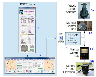
PSTRotator controls the antenna's azimuth and elevation.

Nr. 1. This window displays Moon data. 
Nr. 2. This is the PSTRotator main window.
Nr. 3 is an USB-to-RS232 converter.
Nr. 4 is the rotator controller ERC-3D. PSTRotator sends commands to this box.
Nr. 5a and 5b are rotator control boxes. They control the rotator and supply power to it.
Nr. 6a is the azimuth rotator (Yaesu G-600).
Nr. 6b is the elevation rotator (Kenpro KR-550).

PSTRotator is shareware - you can try it for free, but you pay 20 EUR if used permanently.

Regards from OZ1BXM Lars Petersen
Homepage: oz1bxm.dk

mandag den 7. november 2016

ATF - a Danish ham radio rally

I visited a ham radio rally (the name is ATF) in Odense in November. The town of Odense is situated on the island of Fyn. This town is often used for meetings and conferences, because it is in the center of Denmark. People from Jylland (western part of the country) and Sjælland (eastern part of Denmark including Copenhagen) can drive there within a few hours.

This rally is held annually and it is quite popular among radio amateurs in Denmark. The stuff on display and for sale belongs to the category "general ham radio". Other rallies are more focusing on special branches of our hobby, for example VHF/UHF/Microwave.

There are several attractions when attending a ham radio rally:
  • You can purchase equipment, both home-made and factory-made
  • You can buy all the spare parts and cables you need
  • You can listen to lectures on different subjects
  • You can meet old friends and make new ones
  • You can visit boots manned by specialists (e.g. "50 MHz")

ATF in Odense 2016-11-06.
The picture above shows the crowd in the morning. Everyone is busy checking the offerings on the tables!

Vy 73 from OZ1BXM Lars Petersen
Homepage: http://oz1bxm.dk

tirsdag den 1. november 2016

WSPR on 30 meters - my findings

I let WSPR run on 30 meters during 13 days of October 2016. The purpose was to learn how my antenna performed on 10 MHz.

My antenna is a loop skywire: 43 meters of wire shaped as a rectangle. The antenna configuration is shown below:

My loop skywire antenna.
The WSPR results were not as expected. I hoped to hear more continents. The average number of continents heard per day was 2.2. Not impresssive. I would have expected hearing at least 3 continents each day. 
Continents heard with WSPR on 30 meters (October 2016).
When I compare the results for 30 meters with those of the 40 m band, it is clear that this antenna performs better on 40 meters. 

OZ1BXM Lars Petersen
Homepage: oz1bxm.dk

onsdag den 5. oktober 2016

WSPR on 30 meters

I had my first experience with WSPR in 2009 and I wrote a piece about WSPR on my blog. Three months later, I published another piece: Reaching worldwide with WSPR. Then I moved on to JT65 in order to make real QSO's on the HF-bands. As you know, a WSPR contact does not count as a QSO.

I have been little active on 30 meters (less than 100 contacts), so I've decided to run WSPR on this band. The purpose is to learn how my antenna (loop skywire, 42 m of wire shaped as a rectangle) performs on 10 MHz.

My experiment begins on October 8th, 2016 and is planned to run until the end of the month.

OZ1BXM Lars Petersen
My homepage: oz1bxm.dk

lørdag den 27. august 2016

Code Practice Oscillator

The Code Practice Oscillator pictured below was developed by me. It is simple and easy to build. It is based on the 555 oscillator IC and is powered from a standard 9V battery. The loudspeaker is mounted on a separate PCB and the two boards are connected with metal spacers. The whole assembly requires no cabinet - and that reduces building time!


Homemade Code Practice Oscillator
Training morse code reception is pretty much covered already by the aid of hardware-based morse trainers, PC programs, app's for smart phones and tablets, etc.

Sending morse code is another case. The obvious solution is to use a keyboard and let the software do the job. This solution works, but you will be missing the touch and feel of dots, dashes, and spacing provided by a manual key. I would recommend a novice sending morse code using a real morse key, and move on to more advanced devices and higher speeds at a later time. 
Circuit Diagram
Another benefit of building your own Code Practice Oscillator is the proudness gained from a successful project. Building skills like reading a diagram, soldering components, connecting wires, and mounting a loudspeaker are all learned during this project.

Best regards: OZ1BXM Lars Petersen
Homepage: http://oz1bxm.dk

mandag den 6. juni 2016

How addictive is DXing?

I watched a movie yesterday on Danish television: The Big Year from 2011 starring Steve Martin, Jack Black, and Owen Wilson. Two bird enthusiasts try to defeat the cocky world record holder in a year-long bird-spotting competition. Bird-spotting is about seeing (or hearing) a specific bird species, and writing down the day, time, and location in a log.

The Big Year.
The reason for watching this fine movie was the analogy between the behavior of bird-spotting enthusiasts and ham radio operators, especially DXers. It is a well-known fact in our circles, that DXing can be an obsession to people, and it has the potential of becoming "the meaning of life" - at least for a long time.

A Year of DX.
The Big Year competition for bird-spotters runs from January 1st to December 31th. It is similar to the DX Marathon. The idea of comparing bird-spotters with DXers is not mine. I read it in A Year of DX by Bob Locher, W9KNI.

Regards from OZ1BXM Lars Petersen
Homepage: oz1bxm.dk

mandag den 2. maj 2016

How JT65 surprised me

I've had a strange experience with my HF-antenna. Here follows the story:

Something was wrong with my antenna. I could not achieve the QSOs I was used to. I called people, but they did not answer. Listening was normal, but transmitting suffered. What was wrong?

My HF-antenna is a horizontal wire loop. I measured the resistance of the loop. It was 1.2 ohm as usual. Then my suspicion turned to the ATU which was sitting outdoors under the roof. Could corrosion have harmed the relays? Was there a bad component on the balun PCB?

I took the ATU down and measured the attenuation from input to output using 20 W RF.
  • 3.5-14 MHz close to 0 dB
  • 18 MHz about 0.5 dB
  • 21-28 MHz about 0.7 dB      
The attenuation figures above are normal. The problem was not the ATU.

The balun was the next object to investigate. I discovered that a screw had become loose. It was the screw securing the wire from the balun output to the antenna terminal. The antenna was thus galvanically disconnected from the balun because this particular screw had gone loose! Here was the explanation of the mysterious lack of contacts! Although galvanically disconnected, there was still a small capacitance between the balun terminal and the antenne wire. I estimated this capacitance to be 1 pF or less.
No connection between balun and antenna.
Before I started the repair job, I had three QSOs with the faulty antenna:
  • RA0AUC, 20m, my signal -22 dB, JT9
  • LU8HGI, 15 m, my signal -20 dB, JT65
  • RN6HGN, 15 m, -25 dB, JT9
The missing antenna connection reduced my power from 5 W to about 50-100 mW (estimated). And the 3 QSOs above were all run with that low power! I find that amazing and a tribute to the digital protocols JT65 and JT9, which were both invented by Joe Taylor, K1JT.

Regards from OZ1BXM Lars Petersen
Homepage: oz1bxm.dk
søndag den 10. april 2016

Designing and Building a Two-Tone Generator

I wanted to measure distortion in my 2m SSB-transmitter and PA. A two-tone test generator (see chapter 4.5 in this document) can reveal distortion in linear amplifiers so I decided to build the Elecraft 2T-gen on a piece of Veroboard. The 2T-gen user manual including a circuit diagram is found here.

There are two sine wave oscillators in the Elecraft 2T-gen. The first one is at 700 Hz, and the second one at 1900 Hz. I tested both oscillators with an analog oscilloscope. The 1900 Hz tone appeared perfect on the screen, but the 700 Hz tone showed distortion (clipping), and this is not acceptable in a test generator. Obviously, the problem was too high amplification in the circuit, and this pointed to poor AGC control.

I tried to solve the problem and eliminate the distortion. After some time, I gave up the MOSFET-based AGC and decided to implement a different method: Using a light bulb as automatic gain control. Here is the final circuit diagram:

Two-tone generator: circuit diagram.

I decided to create a new PCB for the two-tone generator. This PCB is visible in the photo below.

The generator is mounted inside an alu-box.
Front plate of generator.
A small 12V 40 mA light bulb worked just fine as AGC. The settling time (stable amplitude) is about 2 seconds. If you are looking for a similar light bulb on ebay.com, I recommend searching for "12V 40mA".

OZ1BXM Lars Petersen
Homepage: oz1bxm.dk

onsdag den 23. marts 2016

My experience with PCB manufacturing in China

I am working on a project which requires a printed circuit board.

First thing was to buy a software package for drawing the PCB layout. I picked Sprint-Layout. The price was fair (50 EUR), and I've had a good experience with another of their products (sPlan for drawing circuit diagrams).

I used Sprint-Layout for drawing the PCB.
    
I decided to try PCB manufacturing in China. I choose PCBgogo mainly because of the user recommendations on their website. Their prices seemed fair, and their product quality seemed just fine. Their minimum order was 5 pieces. I decided to order 10 x PCB single sided, dimensions 100 mm x 48 mm, payment by PayPal.

Logo of the PCB manufacturer.
Once the PCB layout was finished, I created Gerber files using the Sprint-Layout export function. The Gerber files were zipped and uploaded to the PCBgogo homepage. I soon received a mail from a person in the company. I had forgotten to include board outline data and drill data. I created the missing files and uploaded a new zip-file. The new file was approved, and production began.

The finished PCBs were shipped by DHL from China to my address in Denmark. The packet was delivered at my doorstep one week after file upload. That was fast!

PCB made in China.
The final price including shipping turned out to be 4.10 USD per PCB. The quality of the PCBs were excellent. I was a good experience for me letting PCBgogo produce the PCBs. I will certainly do this again when the need for other PCBs arise!

Regards from OZ1BXM Lars
Homepage: oz1bxm.dk

fredag den 4. marts 2016

scQRPions: QRP Challenge Rules

scQRPions: QRP Challenge Rules: Starting January 1st 2016, and each year thereafter, we will be embarking on a challenge to work (not confirm) 100 DXCC entities in 100 days or less.

Remarks from OZ1BXM:

I discovered the QRP Challenge yesterday. You need to work 100 DXCC entities during 100 consecutive days or less. Your start-date and end-date must be within the calendar year 2016.

May-June-July is a good choice for QRP Challenge participation.
The rules of the QRP Challenge are pretty much the same as for the ARRL QRP DXCC diploma. Club membership is not necessary. QSL-cards are not needed - you simply submit a signed log. As of today, there are 13 participants, and only one from Europe. N4MM is in the lead - he worked 100 DXCC in just 8 days!

The QRP Challenge is backed up by the North Carolina DX & Contest Club (NCDXCC), South Carolina DX Association (SCDXA), and Greer Amateur Radio Club (GARC) in South Carolina. Program coordination is by Ariel Jacala NY4G.

I feel tempted to participate. As you can see in the figure above, the months of May-June-July are well suited for an European station like me as there are 4 major contests during this period.

Regards from OZ1BXM Lars Petersen
Homepage: http://oz1bxm.dk/

lørdag den 30. januar 2016

Writing for new hams

I have been a radio amateur for several decades. During all this time, I have collected experience in different fields. I wanted to give something back to the newcomers within this wonderful avocation. So I decided to write some articles aimed at the new ham and publish the material in the Danish national ham radio magazine "OZ". It is my hope, that new hams will be inspired and power up the soldering iron and start build electronic circuits.

My concept is KISS (Keep It Simple Stupid). The builder should be able to get the construction up and running during a weekend. I recommend building circuits without a factory produced PCB and using a Veroboard instead. Flexibility in component placement is maintained this way. 

Sourcing of components is another challenge that faces the new ham. It is an advantage if the circuit can be built using standard components, and that is my goal. A project should not halt due to lack of special parts.

One example of such a beginner's project is the 1 kHz sine oscillator (circuit diagram above). I tried different oscillator circuits before I settled with the phase-shift oscillator. I achieved a stable and clean output by adding buffers between the different filter stages. The result was a simple sine oscillator which is easy to build by new hams. 
The finished 1 kHz sine oscillator.
Regards from OZ1BXM Lars Petersen
Homepage: http://oz1bxm.dk